StarkEffects.com
Articles by Subject Category
Physics Basics Series
- Basics of Classical Mechanics.
- Basics of Quantum Mechanics.
- Basics of Electrodynamics.
- Basics of Optics.
- Basics of Mathematical Tools for Physics.
- Basics of Plasma Physics.
- Basics of Solid State Physics.
Troy Stark's Science & Society Opinion Blog
Concise Articles, Tutorials & Primers on Physics, Math & Technology & Obscure Science Topics
Physics Basics Series
- Basics of Classical Mechanics.
- Basics of Quantum Mechanics.
- Basics of Electrodynamics.
- Basics of Optics.
- Basics of Mathematical Tools for Physics.
- Basics of Plasma Physics.
- Basics of Solid State Physics.
Troy Stark's Science & Society Opinion Blog

Rogowski Coil
This is the theory of operation of the Rogowski Coil which is used for the measurement of fast pulses of current.
The Rogowski Coil is a very simple device for measuring fast, strong electric currents. This article will describe the theory of operation of a Rogowski coil with the basic math showing the simple operation.
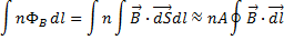
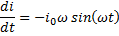
Lets start by following a closed path around a current carrying wire or some other conductive path. According to Amperes law, the line integral of the magnetic field is proportional to the current piercing the surface defined by our closed path:
 Ampere's Law
If
that path coincides with the axis of a solenoid (with the turns small
compared to the path so that the magnetic field  , is essentially
constant over the surface
, is essentially
constant over the surface  of any individual
turn in the solenoid), then
of any individual
turn in the solenoid), then  is parallel to
  and the magnetic
flux linking the turns of the solenoid is proportional to the same
integral:
and the magnetic
flux linking the turns of the solenoid is proportional to the same
integral:
In
this equation  is the area of
each turn of the solenoid and
is the area of
each turn of the solenoid and  is the number of
turns per unit length. By using Faradays law of induction, we can find the
induced
is the number of
turns per unit length. By using Faradays law of induction, we can find the
induced  in our solenoid:
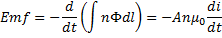
Now
we have an induced in a solenoid
which is proportional to the change in current threading the surface
defined by the axis of our solenoid. This solenoid is a Rogowski loop. By
letting the terminal end of the solenoid trace a path back down the axis of
the solenoid, we avoid and produced by
changing magnetic fields normal to the surface defined by our loop.
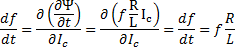
We
also have a circuit consisting of a an inductance  (the solenoid), a
resistance
(the solenoid), a
resistance  and an induced . Describing this circuit is the differential equation:
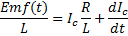
This
is a linear equation in which the right hand side can be turned into an
exact differential by an integrating factor 
If
the right hand side is to be an exact differential, then there exists a
function,  , such that
 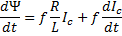 which is valid if
  and
and  . If this is true then
 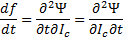 which leaves:
The solution to which is:

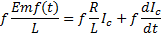
Taking
 to be 1, carrying
out the integration in the exponent and putting the integrating factor back
into the equation above we get the following:
to be 1, carrying
out the integration in the exponent and putting the integrating factor back
into the equation above we get the following:
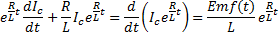
Integrating gives:
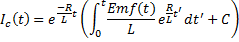
And, now we can write this as:
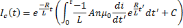
We can solve for the constant of integration by using the current:
Then
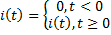
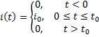
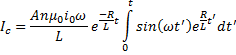
Lets look at an example, such as a square wave current that you might expect from a charged particle beam with a finite length:
Then
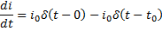
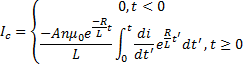
The current in the coil then becomes:
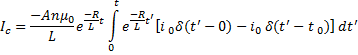
Carrying out the integration and scanning the time through the different regions we get:
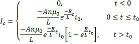
This gives us an output waveform that looks like the following:


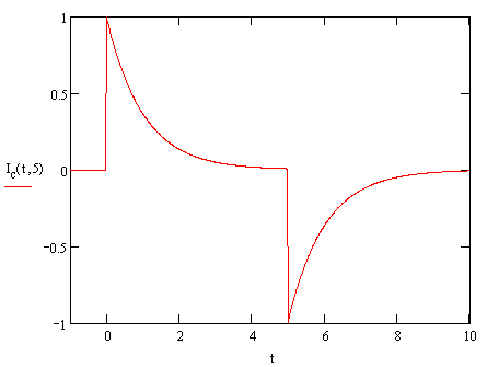
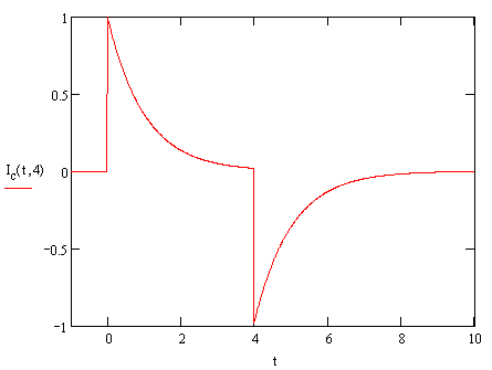
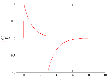
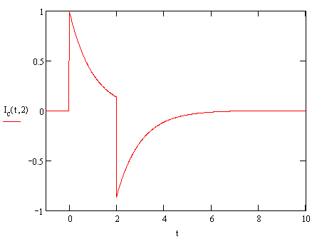
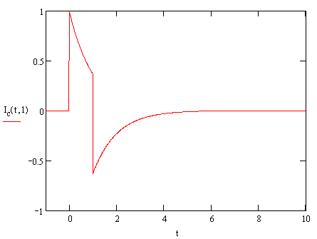
We
can see that if  is small, then in
the central region the output has a spike at zero after which the
exponential causes a very rapid decay to zero. When the time comes that the
pulse ends, we get a negative spike which again decays to zero. This is
exactly what we expect for a differentiating coil with output proportional
to the derivative of the current.
is small, then in
the central region the output has a spike at zero after which the
exponential causes a very rapid decay to zero. When the time comes that the
pulse ends, we get a negative spike which again decays to zero. This is
exactly what we expect for a differentiating coil with output proportional
to the derivative of the current.
We could also try a current described by a ramp function:

In this case the output is zero until time equals zero and any time thereafter it can be described by:
Rewriting this in the voltage output regime:
If is small, then the
output quickly rises from zero to a fixed asymptotic value which indicates
the derivative of the function representing the current to be measured. If is large, however,
this function representing the output does not exactly look like the output
of a self integrating coil, the asymptotic value is larger and the exponential
is more spread out, but we still dont see a ramp function. Here we have
reached a limit; the pulse width is infinite which makes a self integrating
coil impossible since theres no way to make larger than the
pulse width.
For further examples we can look at sinusoidal functions describing the current to be measured.
At times greater than zero:
Then the coil current, and thus the output, for times greater than zero is:
Carrying out an integration by parts yields:
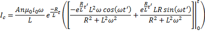
And combining terms:
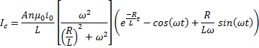
In
this solution the term that dominates is determined by the time compared to the period of the current being
measured. If the term is large
compared tot eh period, then we have a self integrating coil and the
dominant term is proportional to the current being measured, while a
smaller leaves the
dominant term proportional to the derivative of the current being measured.
Note that in the self integrating case the magnitude of the output voltage
is not significantly dependant on the frequency of the input signal while
in the derivative proportionality case the magnitude of the output voltage
definitely does depend on the frequency.
By keeping as small as possible, we can be certain that we are
operating our coil in the self integrating mode for a rather high frequency
current that we most often want to measure.
Quick Science & Math References
- Our Solar System.
- Earth Facts.
- The Metric System.
- Trigonometric Identities.
- Vector & Tensor Identities.
- Explicit Forms of Vector Operators
- Light & Electromagnetic Spectrum.
- Common Laser Wavelengths.
- Human Physiology Facts.
- Human History Timeline
- Geologic Timeline
- Cambrian Explosion
- Life on Earth Timeline
- ASCII Codes and HTML Display Codes
- Thousands of HTML Symbol Codes
- HTML Symbol Codes for Greek Letters
- The Best Way to put Equations on your Web Page
Physics Basics Series
- Basics of Classical Mechanics.
- Basics of Quantum Mechanics.
- Basics of Electrodynamics.
- Basics of Optics.
- Basics of Mathematical Tools for Physics.
- Basics of Plasma Physics.
- Basics of Solid State Physics.
Math Basics Series
- Numbers
- Arithmetic
- Algebra
- Geometry
- Analysis
Technology Basics Series
- Basics of Remote Sensing.
- Basics of Digital Signal Processing.
- Critical Electronic Circuits
- Infrared Imaging Basics
Knowledge Branches
- Information Theory
- How Reading Works in the Brain
- Psychology of Learning
- Logic
WORK IN PROGRESS
- What is the Stark Effect?
- The Chemistry of Love &/or Addiction
- Critical Thinking: How to question what you see, read or hear.
- Aristotle's Prior Analytics - the birth of Logic.
- Optical Solutions, lenses that solve problems
- Fractals
- PTC - Photon Transfer Curve or Mean Variance Analysis
- 3-D Noise
- Laser Primer
- Rail Guns
- Special Relativity
- Radar Technology
- Acousto-optic Cells
- Harmonic Generation for Laser Frequency Doubling (SHG) and Tripling -using non-linear crystals.
- Measurement: Accuracy & Precision.
- Things you should know about computer modeling of physical phenomena!
- Giant Magneto-resistance
- Peltier Cooling
- Pyro-Electric Detectors
- Piezo-Electric Crystals
- Laser Speckle
- FFT and DFT the fast fourier transform and the discrete fourier transform
- Fabry Perot Etalon
- The Hydrogen Atom.
- PCA (Principal Component Analysis)
- Energy per mass in fuels such as Hydrogen, Gasoline, Kerosene, HMX etc...
- Nobel prize winning work on the CCD
- How does a CCD work and what are the normal characteristics of a CCD
- Nobel Prize Winning work on Giant Magneto-resistance
- FROG -frequency resolved optical gating
- Optical Wavefront Sensing
- THz imaging and time-domain spectroscopy
- Camera Calibration
- Laser Designators
- Resampling